-
6
-
2025-09-25 15:20:14
This article provides a detailed explanation of permanent magnet motors from two aspects: internal structure and working principle, enabling a deeper understanding of permanent magnet synchronous motors!
1. Internal Structure of Permanent Magnet Synchronous Motors
• Permanent magnet synchronous motors (PMSM) utilize permanent magnets for excitation (the magnetic field essential for motor operation). They are brushless and require no excitation current, thereby enhancing motor efficiency and power density!
• A permanent magnet synchronous motor typically consists of: stator, rotor, end caps, and other components. As shown below:
• Stator windings are wound around the stator core. By controlling the frequency of the input current to the stator windings, the rotation frequency of the magnetic field can be regulated, thereby controlling the rotational speed.
The key difference between a permanent magnet synchronous motor and a conventional asynchronous motor lies in the rotor structure. Permanent magnet poles are mounted on the rotor, and there are multiple arrangements for positioning these permanent magnets within the rotor. Several primary configurations are described below.
The permanent magnet rotor core still requires silicon steel laminations because permanent magnet synchronous motors are typically driven by inverter power supplies. Even sinusoidal inverter outputs contain high-frequency harmonics; using solid steel would generate eddy current losses.
First Configuration: Surface-Mounted Permanent Magnet Rotor

A rotor equipped with permanent magnet poles mounted on the circumferential surface of the rotor core is termed a surface-mounted permanent magnet rotor. The polarity and magnetic flux direction of the poles are shown in the right diagram of Figure 3, illustrating a 4-pole rotor.
Based on the principle of minimum magnetic resistance—where magnetic flux always closes along the path of least resistance—magnetic attraction drives the rotor's rotation. Consequently, the permanent magnet rotor synchronously rotates with the rotating magnetic field generated by the stator.
Second Form: Surface-Embedded Permanent Magnet Rotor
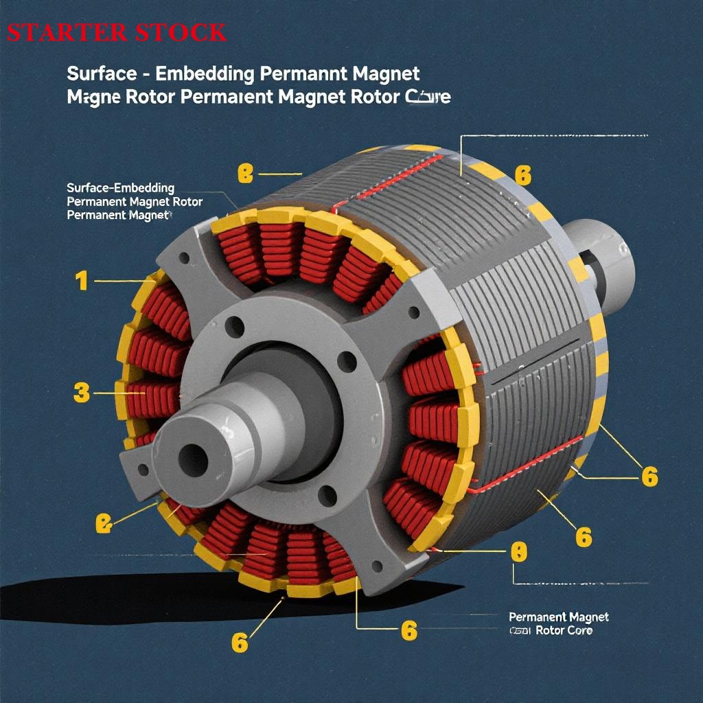
Figure 4 (left) shows another rotor configuration with permanent magnet poles. The permanent magnet poles are embedded into the surface of the rotor core. The polarity of the poles and the direction of magnetic flux are shown in Figure 4 (right). This is also a 4-pole rotor.
Third Form: Internally Embedded Permanent Magnet Rotor
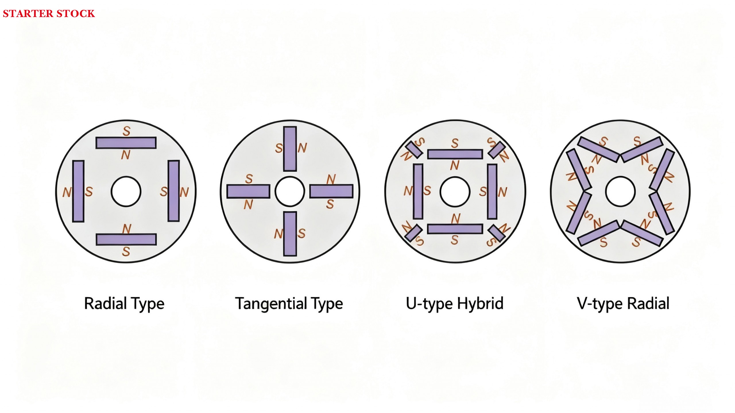
More commonly used in larger motors, this design embeds permanent magnets within the rotor core, termed an internal-embedded permanent magnet rotor (also known as an internal-mounted or internal-embedded permanent magnet rotor). The magnets are installed within slots machined into the rotor core, with primary arrangement configurations shown in Figure 5. Each configuration may also incorporate multi-layer magnet assemblies.
2. Operating Principles of Permanent Magnet Synchronous Motors
Permanent magnet synchronous motors operate in two modes: synchronous operation achieved via variable frequency drives (VFDs), or synchronous operation achieved through asynchronous starting methods.
Permanent magnet synchronous motors cannot be directly started with three-phase AC power. Due to the high rotor inertia, the magnetic field rotates too rapidly, preventing the stationary rotor from initiating rotation in sync with the magnetic field.
2.1 Variable Frequency Drive Method
2.1.1 The motor is powered by a variable frequency drive (VFD). During startup, the VFD's output frequency rises continuously from zero to the operating frequency. The motor speed increases synchronously with the VFD's output frequency. Adjusting the VFD's output frequency directly alters the motor speed, making it an excellent variable speed motor.
2.2 Asynchronous Starting Methods
• Using variable frequency drives for asynchronous starting of permanent magnet synchronous motors significantly increases motor costs.
• The starting and operation of permanent magnet synchronous motors are formed by the interaction of magnetic fields generated by the stator windings, rotor squirrel-cage windings, and permanent magnets.
• For applications requiring no speed regulation, direct three-phase AC power supply is achieved by adding a squirrel-cage winding to the permanent magnet rotor.
• At rest, applying three-phase AC to the stator windings generates a rotating stator magnetic field;
• Asynchronous Start — The stator field rotates first, driving the “starting winding” (resembling wheel teeth) on the rotor to generate thrust, accelerating the rotor from standstill;
• Synchronous Engagement — When the rotor speed approaches the magnetic field speed (approximately 90%-95%), the “permanent magnets” on the rotor are attracted by the magnetic field, pulling the rotor to match the magnetic field's speed;
• Stable Operation: Subsequently, the rotor and magnetic field rotate synchronously. The starting winding “rests,” relying on the permanent magnets to maintain a stable rotational speed.