Comprehensive Analysis of Electric vehicle Controller Failures
-
8
-
2025-10-26 17:56:32
With electric vehicle ownership surpassing hundreds of millions, controller failure rates—as the “nerve center”—reach as high as 12%. When riding, sudden power loss, brake failure, abnormal noises, or power cuts occur, 80% of faults stem from damage to core controller components. This article provides an in-depth breakdown of the entire controller repair process, helping you quickly identify fault types and perform precise repairs.
I. Fault Identification: 5 Major Symptoms Comparison Chart
1. Power Cliff-like Decline: Motor RPM suddenly stalls during normal acceleration; dashboard battery display shows abnormal fluctuations
2. Brake Failure Crisis: Motor continues power output during braking, posing severe safety risks
3. Lighting System Malfunction: Turn signals flash irregularly; warning lights activate randomly
4. Charging Alert: Dashboard displays “Charging” yet repeatedly trips during charging
5. Abnormal Noise & Power Cut: Metallic grinding sounds accompanied by sudden power loss (immediately disconnect power)
Maintenance Key Points: It is recommended to bring the original factory manual for circuit diagram reference, with a focus on checking the stability of the 12V main control voltage. Repair data from a certain brand indicates that 78% of failures stem from poor solder joints caused by overheating of the MCU chip.
II. Root Causes: Dissection of Three Core Components
(1) Hall Sensor Assembly (42% Failure Rate)
1. Testing Method: Measure the resistance value of the three-wire assembly with a multimeter (normal range: 1.2-1.8kΩ)
2. Repair Technique: Employing a “hot air gun + flux” combination for soldering increases success rate to 89%
(2) Power MOSFET Array (35% Failure Rate)
1. Key Parameters: Forward voltage drop ≤20mV, leakage current<50μA
2. Testing Pitfall: Visual inspection alone yields less than 60% pass rate for solder joints
3.Professional Repair: Requires dynamic load tester to simulate actual operating conditions
(3) Power Management Module (Failure Rate: 23%)
1. Protection Mechanism: Triple protection circuit for overvoltage/overcurrent/short circuit
2. Maintenance Focus: Prioritize inspecting voltage fluctuations at the output terminals of the LM2596 voltage regulator chip
3. Data Support: Statistics from a maintenance platform indicate that 85% of module failures stem from filter capacitor failure
III. Repair Solutions: 5 Scenario-Based Workflows
Scenario 1: Sporadic Power Loss (61% of cases)
1. Emergency Response: Disconnect battery negative terminal for 10 minutes, then restart system
2. Professional Repair:
- Inspect MCU crystal oscillator circuit (common failure point)
- Clean oxidation layer from 12V power input terminal
- Replace 0402-package capacitors (Recommended model: TDK C0G)
Scenario 2: Persistent Output Abnormalities (29% of Cases)
1. Data Diagnosis: Record motor current waveforms during fault cycles
2. Repair Steps:
- Check Hall signal phase difference (standard value ±5°)
- Test PWM waveform duty cycle (normal range 15%-85%)
- Replace driver IC (recommended: TI SN6501)
Scenario 3: Thermal Shutdown (8% of cases)
1. Critical Checks:
- Ambient vs. chip temperature differential (must >15°C)
- Heat sink thermal conductivity (>5W/m·K)
2. Upgrade Solution: Install thermal protection circuit (approx. 35 RMB cost)
IV. Safety Warnings: 3 Major Maintenance Restrictions
1. Prohibited Practices:
- Using non-original soldering irons (temperatures >300°C may damage PCB)
- Exposing soldering power cables (increases leakage risk by 7x)
- Not wearing anti-static wrist straps (static damage rate as high as 63%)
2. Data Support: Statistics from a major repair chain indicate that non-compliant operations increase return rates by 40%.
V. Preventive Maintenance: Annual Maintenance Guide
1. Core Items:
- Inspect connector oxidation (clean with anhydrous alcohol)
- Test insulation resistance (≥100MΩ is acceptable)
- Replace ceramic capacitors (recommended brand: Murata)
2. Daily Maintenance
Core Maintenance Principles: Waterproofing, Heat Protection, Shock Resistance, Overload Prevention
Daily Usage Habits
Smooth Acceleration, Avoid Sudden Surge:
Avoid twisting the throttle grip to full throttle instantly. Sudden high currents are the primary cause of damage to the controller's MOSFETs and capacitors. Develop the habit of accelerating slowly and smoothly.
Minimize Frequent Braking and Acceleration:
In congested areas, avoid repeated “start-brake-start” cycles. Each acceleration subjects the controller to a current surge.
Push-Start with Assistance:
When stationary or climbing a hill with load, first pedal or push the bike slightly before engaging electric power. This significantly reduces the controller's startup load.
Do not charge immediately after stopping:
Especially in summer or after long rides, the controller and motor are hot. Wait 15-30 minutes for them to cool naturally before charging to avoid adding heat.
Environmental and Storage Precautions
Absolute Waterproofing:
Avoid Deep Water Areas: When water depth exceeds half the wheel rim height, avoid forcing passage. Standing water can easily seep into the controller through wiring ports and cooling vents, causing short circuits.
Restrictions on the use of high-pressure washers: When you clean the vehicle, you should never use a high-pressure washer to spray directly at areas where controllers may be located, such as the seat bucket or footrests. Use a damp cloth instead.
Rainy weather storage: The covering of the middle section of the body with a plastic sheet is recommended in the event of the vehicle being used a lot or kept outside in the rain.
Avoid prolonged sun exposure:
During summer, the parking of cars should be in shaded areas wherever possible. Basically, if you leave your car in the sun for ages, the insides of the car are going to get really hot. This speeds up the ageing process and can cause them to break.
Keep the car clean and dry:
The controller casing should be given a regular dust and dirt clean to make sure that heat is spread out as well as possible.
3. Cost Comparison: Regular maintenance reduces unexpected failure probability by 50%.
-
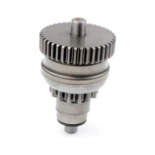
Starterstock Starter Drive Bendix for Beta Enduro RR/Xtrainer
-
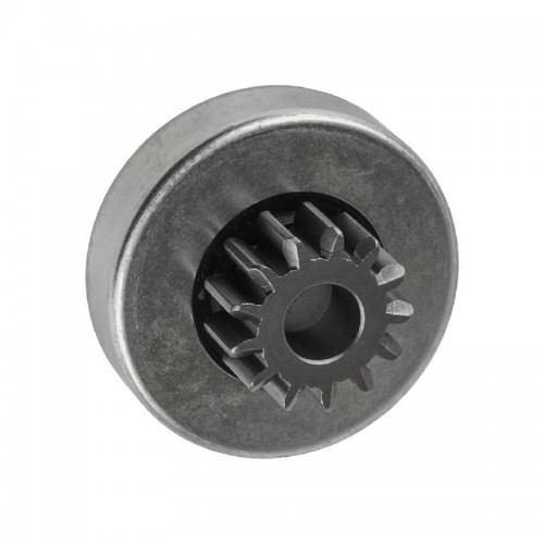
Starterstock Starter Drive Bendix for Sea-Doo Speedster 200 Twin 4-TEC
-
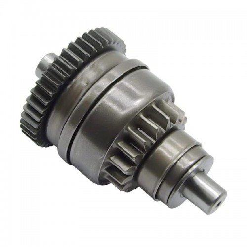
Starterstock Starter Drive Bendix for Polaris Trail Blazer/Sportsman
-
Starterstock Starter Drive Bendix for Kawasaki Jet Ski 650-1100
-
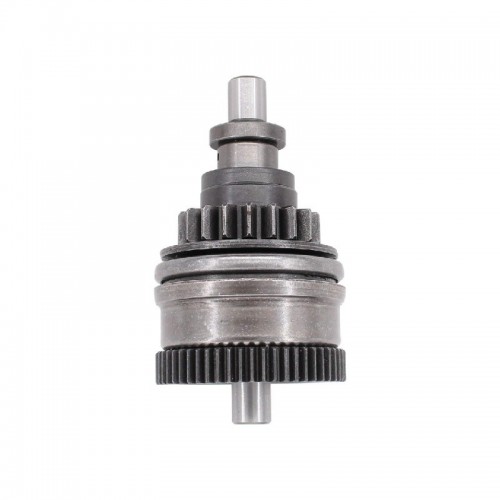
Starterstock Starter Drive Bendix for Yamaha WaveRunner/WaveRaider
-
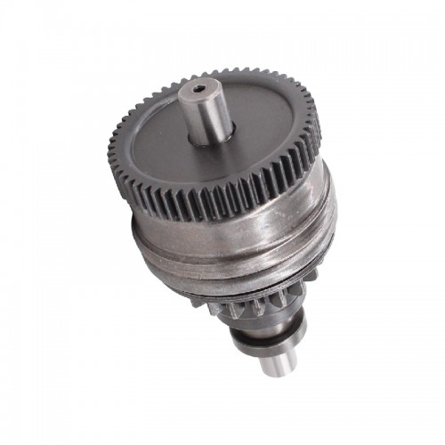
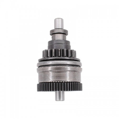
Starterstock Starter Drive Bendix for Polaris Sportsman/Ranger
-
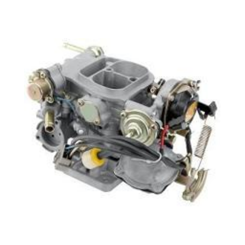
CARBURETOR LY-010011 for TOYOTA 4Y HILUX
-
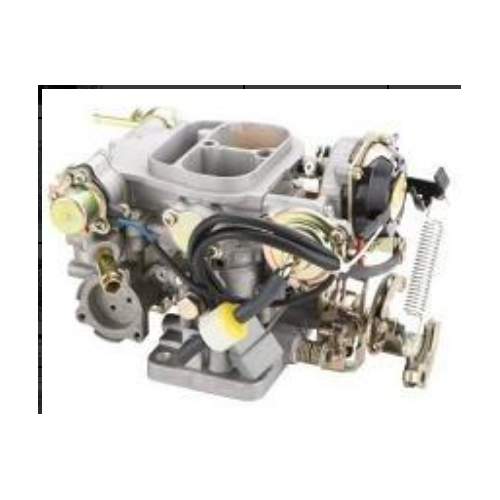
CARBURETOR LY-010010 for TOYOTA 3Y HIACE
-
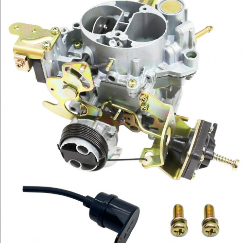
CARBURETOR LY-010009-A for PEUGEOT 405 ZINC
-
CARBURETOR LY-010009 for PEUGEOT 505 ZINC
