-
21
-
2026-05-07 15:05:43
As a B2B distributor of ATVs (all-terrain vehicles), mastering the testing and replacement of starter solenoids enables you to respond quickly to downstream customers’ after-sales needs and enhance customer trust, while also allowing you to accurately diagnose product failures and optimize inventory management. The ATV starter solenoid is one of the three core components of the starter motor. Essentially a combination of an electromagnet and a switch, it is responsible for connecting the main circuit and driving the drive gear to engage with the engine flywheel. Its performance directly determines the reliability of the ATV’s starting process, and it is also one of the most frequently inquired-about faulty components by downstream repair shops. This guide, tailored to the distributor’s context, provides a concise and actionable testing and replacement process that balances professionalism with practicality.
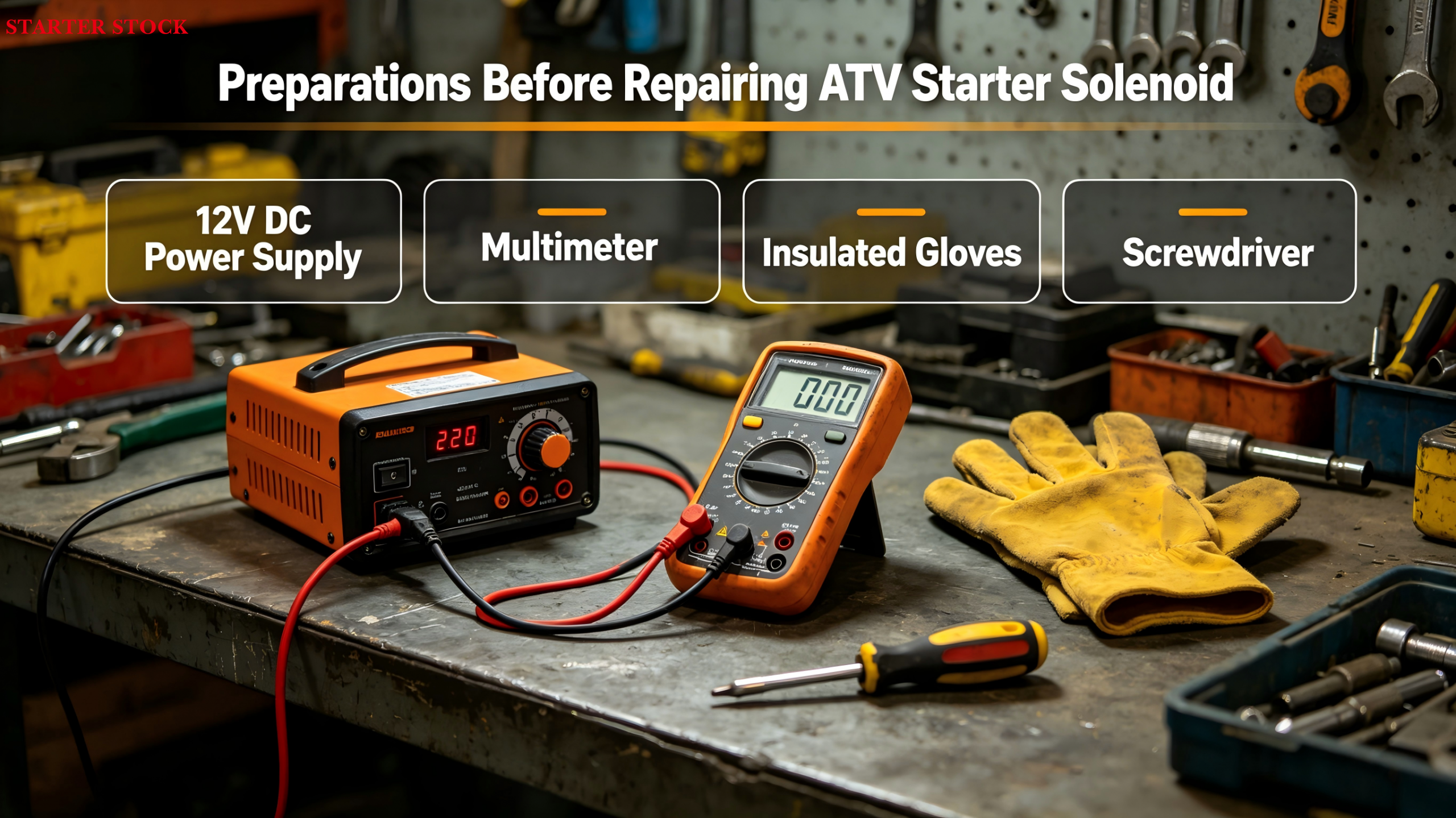
Before testing, prepare the following basic tools: a 12V DC power source (a spare battery can be used), a mBasic tools shall be prepared before the test: 12V DC power supply (standby battery is available), multimeter, insulated gloves and screwdriver. The core precautions are to disconnect the negative pole of ATV battery before operation to avoid short circuit damage to components or potential safety hazards, This is also a critical safety point to communicate to downstream customers. The test consists of four core steps that allow for a quick determination of the solenoid switch’s condition, helping distributors rapidly troubleshoot issues reported by customers.
Step 1: Engagement Function Test. Connect the solenoid switch’s "Terminal 50" (thin red wire) to the power supply’s positive terminal and the housing to the negative terminal. Under normal conditions, a clear "click"sound should be heard as the switch engages, and the drive gear should pop out. If there is no sound or the gear does not move, this indicates an open circuit in the solenoid coil or mechanical jamming, and the product should be deemed defective. Limit the power connection time during testing to 3–5 seconds to prevent coil overheating and damage. This method helps distributors quickly identify non-conforming products in their inventory.
Step 2: Hold Function Verification. After engagement, disconnect the power from"Terminal 50.”If the gear remains extended, the hold coil is functioning normally; if the gear retracts immediately, check for a short circuit in the hold coil. Note that the hold time should not be too long to prevent coil burnout—this is an operational detail often overlooked by downstream repair shops, so distributors should emphasize it in after-sales guidance.
Step 3:The third step is continuity measurement. Measure the "30 terminal" (thick red wire, connected to the battery) and "C terminal" (connected to the starter stator) with the resistance gear of the multimeter. Under normal conditions, it should be open circuit (infinite resistance), and it should be connected when it is pulled in (resistance close to 0). If it is normally conductive, it indicates that the contact is sintered; If the circuit is still open after closing, the electromagnetic switch needs to be replaced directly. This judgment standard can help distributors accurately respond to customer fault inquiries and reduce ineffective communication.
Step 4: Check the return mechanism. After disconnecting all power sources, the gear should automatically retract to its original position; if it gets stuck, the return spring may be faulty or there may be foreign objects in the gear track. You can manually press the gear to test it; if there is excessive resistance, it is recommended to disassemble and clean it or replace the spring to avoid damaging the gear by forcing it open.
The replacement procedure must follow the sequence of “power off – disassembly – installation – testing.” It is compatible with all mainstream ATV models, and distributors can share this information with their downstream repair customers. First, disconnect the negative battery terminal, remove the mounting bolts of the solenoid switch, and record the positions of the terminal connectors (it is recommended to take a photo for reference) to avoid wiring errors; Next, disconnect all terminals, remove the old solenoid switch, and clean dust and oxidation from the mounting area to ensure the mounting surface is smooth.
When installing a new electromagnetic switch, first fix the bolt (the tightening force is moderate to avoid damaging the thread), and then connect the wiring terminal according to the recorded position to ensure that the wiring is firm and free of looseness. Focus on checking the contact between the main terminal and the contact to prevent the startup fault caused by poor contact. After installation, reconnect the negative pole of the battery, conduct pull in, continuity and return tests, and start ATV verification after confirming that the function is normal to ensure that the startup is smooth and normal.
For B2B distributors, two additional core suggestions are added: first, in the inventory management, the batch electromagnetic switches can be sampled and tested regularly, focusing on the inspection of the pull-on function and coil status, so as to avoid unqualified products flowing downstream; Second, in the after-sales support, this test and replacement process can be synchronized to the cooperative maintenance provider. At the same time, the customer can be reminded that electromagnetic switch failures are mostly caused by coil aging, contact ablation or mechanical stagnation. The terminal oxide can be cleaned regularly in daily life to extend the service life.