Home  >  Club  >  Technical Q&A   >  Car parts

STARTER MOTOR

LV3
  • 27

  • 2025-08-01 10:37:48

A starter motor is a specialized electric motor that operates for short periods of time. Its core function is to convert electrical energy (usually from a battery) into mechanical energy, driving the engine crankshaft and completing the engine starting process (intake, compression, ignition/fuel injection). Its principle is based on electromagnetic induction, and its design must balance high starting torque, short-term overload capacity, and engine compatibility.

1. Working Principle of a Starter Motor

The core of a starter motor is a DC motor (AC is used in a few special cases, but DC is the mainstream because batteries provide DC power). Its operating principle is based on the laws of electromagnetic force and electromagnetic induction, and can be broken down into the following three parts:

1.1 Basic Electromagnetic Principles

The rotation of a DC motor relies on the law of force on a current-carrying conductor in a magnetic field (the left-hand rule):

  • The stator (magnetic field) generates a constant magnetic field (generated by permanent magnets or energized field windings);
  • When current flows through the rotor (armature) windings, they become current-carrying conductors. They are subjected to electromagnetic forces in the stator magnetic field, generating electromagnetic torque that drives the rotor to rotate;
  • To ensure that the direction of the torque remains constant, the commutator and brushes convert the external DC current into an alternating current in the rotor windings, causing the rotor to rotate continuously.

1.2 Starter Motor Characteristics

The starter motor must meet the "short-term, high-load" requirement: During engine startup, the crankshaft resistance torque is high (especially during cold starts due to high oil viscosity and high compression resistance). Therefore, the starter motor must have high starting torque (typically several times the rated torque) and be able to operate stably under low voltage (the voltage drops as the battery discharges).

Most popular starter motors use series-wound DC motors, whose characteristics perfectly match starting requirements:

  • In a series-wound motor, the field winding and armature winding are connected in series, with current flowing through both simultaneously.
  • Torque characteristics: Electromagnetic torque T ∝ I² (I is current), meaning that torque increases sharply as current increases, making it suitable for high-load scenarios during starting.
  • Speed characteristics: Speed n ∝ U/I (U is voltage), meaning that speed increases as load decreases (in the later stages of starting, as the engine performs its own work and the load decreases, the motor speed increases without overloading).

1.3 Complete Operation Process

The starter motor's operation requires coordination with the transmission mechanism and control device. The process is as follows:

  1. Turn on the starter switch (such as a car's ignition switch), energizing the control device (electromagnetic switch). The pull-in coil and the holding coil generate magnetic force, pulling the core.
  2. The core drives the transmission mechanism (pinion) to engage with the engine flywheel ring gear (to prevent idling and gear snagging).
  3. When the core moves to its limit position, the motor's main circuit (battery → motor winding) is connected, causing the series-wound motor to rotate, driving the flywheel through the pinion, which in turn drives the crankshaft.
  4. After the engine starts (and its speed exceeds the motor's), the one-way clutch in the transmission mechanism disengages (to prevent damage to the motor due to reverse engine drag).
  5. Release the starter switch, de-energizing the electromagnetic switch, causing the pinion to return to its original position, and the motor to stop.

2. Key Design Points for Starter Motors

Starter motor design must focus on meeting engine starting requirements. The core objective is to balance torque, speed, size, and reliability. The specific steps and key parameters are as follows:

2.1 Design Input: Clarify Starting Requirements

First, determine the starter motor's performance specifications based on the engine parameters. Key inputs include:

  • Maximum engine starting torque Teng (dependent on displacement, compression ratio, and cold start temperature; for example, approximately 50-80 N·m for a 1.5L gasoline engine);
  • Minimum starting speed nmin (approximately 50-100 rpm for gasoline engines, 150-300 rpm for diesel engines);
  • Supply voltage U (12V for passenger cars, 24V for commercial vehicles/heavy machinery);
  • Operating environment (temperature: -40°C to 85°C; vibration, humidity, etc.).

2.2 Core Parameter Design

Based on the input requirements, calculate the key parameters of the motor:

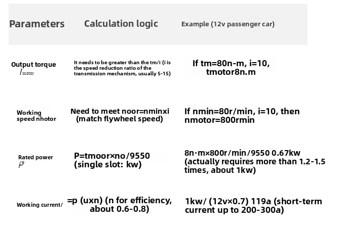
2.3 Design of Key Components

The starting motor consists of three parts: a DC motor, a transmission mechanism, and a control device. The design of each part needs to be optimized in a coordinated manner:

(1) DC Motor Design

  • Stator (magnetic field part):
    • Excitation mode: series excitation (mainstream), the excitation winding is connected in series with the armature, wound with thick wire (high current), and with a small number of turns (reducing resistance);
    • Magnetic circuit design: the core is laminated with silicon steel sheets (reducing eddy current loss), ensuring the magnetic field strength (matching with the current and number of turns), and avoiding magnetic saturation (affecting torque output).
  • Rotor (armature):
    • Winding: multiple turns of coils are connected in parallel (increasing current capacity), and the cross-sectional area of the wire must meet the short-term high current (such as 200A);
    • Commutator: copper, the number of sheets matches the number of winding turns to ensure reliable commutation (avoiding excessive spark erosion);
    • Iron core: laminated silicon steel sheets, the slot design needs to balance the winding space and magnetic circuit area.
  • Brushes and bearings:
    • Brushes: Use graphite-copper alloy (good conductivity and wear resistance), and the pressure should be moderate (too tight will wear quickly, too loose will cause poor contact);
    • Bearings: For short-term operation, sliding bearings (low cost) or rolling bearings (high reliability scenarios) can be selected.

(2) Transmission Mechanism Design

The core function is "transmitting torque + preventing back-drag", and the key components are one-way clutch and reduction gear:

  • Reduction gear: Usually a spur gear, the reduction ratio i needs to match the motor speed and flywheel speed (such as motor 800r/min → flywheel 80r/min, i=10);
  • One-way clutch: Commonly used roller type (simple structure) or friction plate type (large torque transmission), to ensure automatic separation after the engine starts (speed > motor) to avoid motor overspeed damage.

(3) Control Device Design

The core is the electromagnetic switch, which is responsible for controlling the synchronization between the motor power supply and the gear meshing:

  • Coil design: Contains a pull-in coil (high current, pulling the iron core) and a holding coil (low current, maintaining meshing), ensuring reliable attraction under 12V/24V;
  • Contact design: The main contacts must withstand hundreds of amperes of current (made of silver alloy, resistant to ablation), and the auxiliary contacts control the on and off of the coil;
  • Mechanical travel: The distance the iron core moves must be precise (to ensure that the gears are fully engaged before connecting to the main circuit to avoid tooth chattering).

2.4 Reliability and Environmental Adaptability Design

  • Low-Temperature Performance: Battery voltage drops at low temperatures (e.g., a 12V battery may drop to 9V at -30°C). Winding resistance needs to be optimized (by reducing wire length or increasing cross-sectional area) to ensure sufficient torque output even at low voltages.
  • Vibration and Shock: The mounting structure needs to be strengthened (e.g., by using rigid brackets), and the clearance between bearings and gears needs to be reasonable to prevent vibration-induced seizures.
  • Short-Term Overload: The motor is designed for short-term operation (typically ≤30s). Complex heat dissipation is not required, but winding insulation must be guaranteed to withstand high temperatures (e.g., 150°C).

click 27Reply 0 Original post 08-01 10:37

Post Reply

Other Circles

  • Car parts
  • Motorcycle parts
  • ATV parts
  • Garden Tools parts
  • E-Motorcycle parts
  • Yacht parts
  • Snowmobile parts
  • Electric Vehicle parts
  • Robot parts
  • Household motors