
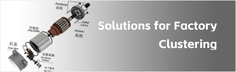
Structure of the Hysteresis Dynamometer:
The hysteresis dynamometer consists of:
A hollow-cup hysteresis rotor
Inner and outer stators
Front and rear end caps
A force measurement mechanism
Bearings
The hysteresis hollow-cup rotor is a special metal rotor made from rare-earth-based materials. After heat treatment, it achieves a single-domain or near-single-domain microstructure, giving it a high coercivity.
When the magnetic domains (magnetic molecules) in the rotor rotate within the air gap, their orientation changes with the external magnetic field direction at different positions. However, due to the high friction between magnetic domains, they cannot realign immediately with the external magnetic field when the rotor is repeatedly magnetized, resulting in a hysteresis angle between the magnetic domains and the external field. This hysteresis effect generates a torque, which is non-frictional in nature.
The hysteresis dynamometer is composed of:
A hysteresis brake mounted on a bearing housing
A torque sensor
A speed sensor
Testing Process:
During testing, the motor under test drives the rotor inside the brake to rotate. When the brake is energized with an excitation current, its inner and outer stators apply a braking torque to the rotor (i.e., the motor under test) through the air gap.
At the same time, the brake undergoes slight deflection, causing micro-strain in the sensors. The torque sensor converts the torque into an electrical signal, while the speed sensor converts the rotational speed into an electrical signal. These signals are then displayed on the LCD screen as measured values.


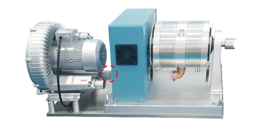
HZC-G type blower-cooled hysteresis dynamometer
US$ 6000.00 / 1 Piece
1Piece Minimum order
Brand:
LANLING
About this item
- All models in the ZC-G series have identical external dimensions to their corresponding HZC series counterparts. The only difference is the addition of an air inlet port for connecting a blower (as indicated by the red dashed line in the figure above). Hysteresis dynamometers are suitable for testing motors with medium and small power ratings. Their torque output remains unaffected by rotational speed, allowing for comprehensive testing from no-load to full torque conditions. Hysteresis dynamometers are available in four types: HZC type: Available in both fan-cooled and natural-convection cooling configurations. HZC-Q type: Equipped with compressed air cooling. HZC-G type: Features blower-cooled operation. HZC-Y type: Utilizes water cooling.
- A hysteresis dynamometer is a brake-type dynamometer (torque machine) designed based on electromagnetic torque technology. It applies a torque load to the motor under test and absorbs its power, functioning as a rotational torque-to-static torque converter. Both the speed sensor and torque sensor are installed on the dynamometer, which converts the speed and torque of the motor under test into pulse signals and analog signals, respectively, and transmits them to the dynamometer controller for display.
- When the motor under test drives the hysteresis dynamometer to rotate, all the power output by the motor is absorbed by the hysteresis dynamometer and converted into heat energy, which is then dissipated via a radiator and an external cooling fan.
- During operation, the controller supplies an excitation current to the hysteresis dynamometer. When current flows through the internal coils of the dynamometer, it generates magnetic flux lines, forming a closed magnetic circuit that passes through the stator teeth, air gap, and rotor hysteresis cup. Since the magnetic flux is denser at the salient pole teeth and sparser between the teeth, when the rotor rotates, an induced electromotive force (EMF) is generated in the hysteresis cup, producing eddy currents. The interaction between these eddy currents and the magnetic field generates a torque, which serves as the load torque.
- The magnitude of this torque depends only on the excitation current supplied by the controller to the dynamometer coils and is essentially independent of the rotational speed at which the motor under test drives the dynamometer.
Jiangsu Lanmec Technology Co., Ltd
2 years
China
Avg Response Time: ≤24 h
Business Type: Technical Services
Chat
Products related to this item
Latest Products from this Supplier


Contact Supplier
Jiangsu Lanmec Technology Co., Ltd
| Address | 222 Long'an North Road, Haian,Nantong,Jiangsu,CHINA | ||||
|---|---|---|---|---|---|
| Homepage Address | https://www.starterstock.com/shop/lanling/ | ||||
| Other Homepage Address | |||||